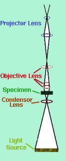
The optical microscope remains the fundamental tool for phase identification. The optical microscope magnifies an image by sending a beam of light through the object as seen in the schematic diagram of Figure 1. The condenser lens focuses the light on the sample and the objective lenses (10X, 40X, . . . , 2000X) magnifies the beam, which contains the image, to the projector lens so the image can be viewed by the observer.
In order for any specimen to be observed, the sample must first be ground using sandpaper of different grain sizes. Then the sample needs to polished into a mirror like image and then etched with a solution for a certain length. Careful technique is critical in sample preparation for without it, the optical microscope is useless.
The following optical micrographs represent steel at certain compositions on the iron-iron carbide phase diagram. Figure 2 is the alpha ferrite form of steel which is stable at room temperature and has a BCC crystal structure.
"Ferrite experiences a ploymorphic transformation to FCC austenite, or gamma iron at 912 degrees Celsius, Figure 3.
At the eutectoid compostion for steel, a formation containning alternating layers of lamellae of the two phases (alpha ferrite and Fe3C) forms called pearlite. Figure 4 is an optical micrograph of a proeutectoid cemmentite (Fe3C) and pearlite. Proeutectoid cemmentite is the cemmentite that form prior to the eutectoid reaction.
http://www.eng.vt.edu/eng/materials/classes/MSE2094_Notebook/
96ClassProj/experimental/