Virginia Polytechnic Institute and State University
ESM 4714 Fall 2000
Christopher W. Thornton
|
"Visualizing the Discrepancy
between Physical and Virtual Measurement of the Six Degrees of Freedom
in the CAVE"
|
Building Instructions for the CAVE Measuring Device
Materials Required:
- 4" ID PVC pipe, cut into the following lengths: 5¹ 10.125",
4¹ 10.125", 3¹ 10.125" and 2¹ 10.125"
- 4" ID PVC cap
- 1.25" ID PVC pipe cut into one 7.5" and two 0.5" lengths
- 1.25" PVC threaded coupler
- four 4" PVC toilet mounts
- four 1.5¹ x 1.5¹ sheets of 0.75" plywood
- twenty-four #8 1.5" lag bolts (stainless steel)
- PVC pipe glue
- Velcro
Instructions:
The PVC toilet mounts are affixed (using the lag bolts) to the exact centers
of the 1.5 foot square sheets of plywood. Each length of 4 inch ID PVC pipe
is then attached to the toilet mounts (one per mount) with the PVC glue. Next,
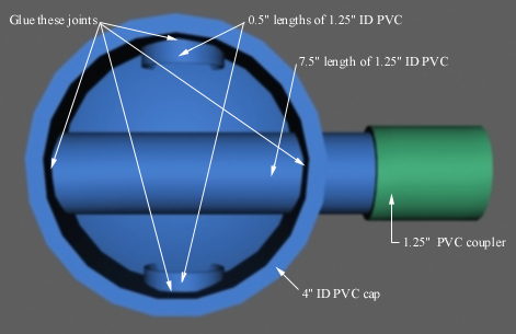
drill four holes (90 degrees apart) in the 4 inch ID PVC cap. Mount (using the
PVC glue) the two 0.5 inch lengths of 1.25 inch ID PVC pipe into two opposing
holes. Make sure the two lengths of pipe are mounted flush with the outside
of the PVC cap. Slide the 7.5 inch length of 1.25 inch ID PVC pipe through one
of the remaining opposing holes, seating it through the opposing hole (mounting
it with the PVC glue) and flush with the outside of the PVC cap. The edges of
the above pipes can be sanded to give a better appearance. Mark the tops of
the 4 inch ID PVC pipe in 45-degree increments, choosing one face each as the
zero point. Imprint the cap assembly with an indication, near the bottom edge,
with a sighting line. Mark the protruding end of the 7.5 inch length of 1.25
inch ID PVC pipe in 45-degree increments. Making sure that the lines are longer
than 1.5 inch long. Sand the inside of the 1.25 inch PVC threaded coupler, so
the friction is reduced between it and the 7.5 inch length of 1.25 inch ID PVC
pipe. Then sand one side of the 1.25 inch PVC threaded coupler flat (in order
to mount the tracker later). Affix Velcro to the flat area.
The image below is a graphical representation of the instructions for constructing
the rotating cap of the CAVE measuring device.
*Note: " = inch