In this problem, we are particularly interested in visualizing the deformations in the plane of the cross-section of the cylinder. A cylinder is considered to be thick-walled if the thickness exceeds the inner radius by more than 10 percent. (Ugural p. 329) For a thick-walled cylinder, the radial and tangential stresses vary significantly with the radius. The deformation is influenced by stresses in the tangential and radial directions, the radial position, and the material constants, as can be seen from the equation for displacement. (Seely p. 305)
In this equation, u is the displacement in the radial direction, rho is the radial distance from the center of the cylinder. The displacement is also dependent on the material constants: the elastic modulus, and Poission's Ratio. The stresses in the radial and tangential directions vary with the radius, and are controlled by the inner and outer pressures, and the inner and outer radii. Due to the symmetry of the problem, the deformations are only in the radial direction.
The following equations for radial and tangential stress (Seely p. 299) are derived from Hooke's law, and therefore are only valid while the material is in the elastic region.
In these equations, p1 and p2 are the inner and outer pressures, r1 and r2 are the inner and outer radii, and rho is the radial distance from the center.
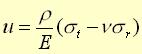
The Java applet I created for the pressure vessel uses the preceding equations to show the stress and deformation on the cylinder for a particular load. The user interface has an input panel where to enter values for the inner and outer radius in millimeters and the inner and outer pressures in MPa. The input panel also has a drop down listbox, which allows the user to choose between several materials, such as steel, aluminum, lead, and PVC. The material constants are stored internally in the program, so that the user will not have to refer to handbooks in order to choose reasonable values. The user must then click on the apply button to update the values. Once the values are entered, the load can be applied by pressing the start button. The pressures are gradually increased from zero to the input pressure, and the view of the results changes with increasing pressure.
This applet uses internal frames, as shown in Figure 3 below, which are simply windows inside of other windows. There are three frames that display the results of this problem, and the user can resize and arrange them depending on what they want to see. The first window shows the cross-section of the cylinder, where the size of the cylinder is scaled to fit in the frame. The cross-section changes as the user increases or decreases the load. For most materials in the elastic region, these deformations are barely noticeable, but it is helpful to see the thickness of the cylinder compared to the diameter. To see how an element of material deforms in the cross-section, it is helpful to have a magnified view. There is another window, which shows a zoomed-in view of the cross-section. The user can use the mouse to draw a pattern of points in this region, and watch the deformation as the load is increased. For comparison of the deformations and stresses, another window was created to show the stresses as a function of the radial position. As the load changes, the graph of the radial and tangential stresses also changes. As with all of the applets, there buttons to stop the animation at points of interest.
Figure 3: Cylindrical Pressure Vessel
In order to draw the images on the screen, the Java program must convert the values that are generated from the equations to pixel locations on the screen. There are functions available in Java to draw lines, rectangles, and ellipses for given pixel values. The Java program also uses a counter, which is incremented for each time step. The input pressures are divided by the total number of steps to determine a change in pressure. This delta value is multiplied by a time step to give pressure. The three display windows are redrawn for each step, creating an animation of the problem. For given inner and outer pressures, and by using the inner radius, the displacement equation gives the change in the inner and outer radii. For the cross-sectional view, the Java program redraws and fills the circles that make up the cylinder each time the pressure changes.
In the magnified view, the user sees a square that physically represents one millimeter in width. The user is able to click in this square to create points. Movement of these points corresponds to deformation of the material. The center of the square is a reference point that moves with the cylinder, and all deformations are relative to that point. In order to apply the elasticity equations, the points must be converted to the coordinates of the problem, and then changed back to the display coordinates.
When the user clicks with the mouse, the point is returned in display coordinates, multiplied by a scaling factor, and added to an array of points. The displacement is calculated at each point on the screen for the different pressures. The Java program then determines the radial position of the point relative to the center of the cylinder. This is done by vectorally adding the center point of the square to the point of interest, and converting the result to polar coordinates. The displacement can then be calculated from the displacement equation. To get the new position of the point, the displacement is converted to Cartesian coordinates, added to the original position and the displacement of the center point is subtracted. Before redrawing the point on the screen, the points are converted to pixel locations. Each point is drawn as an ellipse, where the center and a corner of the rectangle that bounds the ellipse are specified.