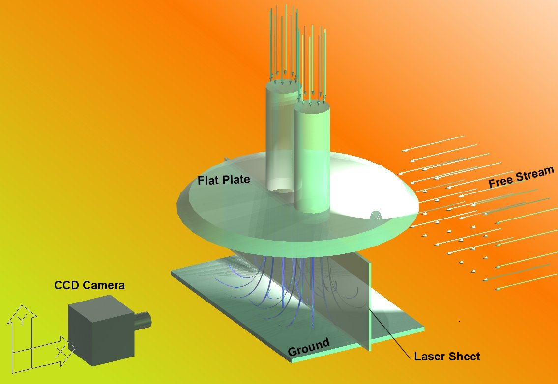
This image
illustrates the experimental setup used to conduct this experiment. The
model used is a beveled-edge disk with 0.254m diameter of the lower
surface as shown in Fig.1. Two cylindrical tabs each of 1.95cm diameter
were flushed with the lower surface of the disk. A 0.305x0.305x0.305m tank
is used to provide for constant head and drive the desired flow through
the tabs. The two tabs were connected individually to the bottom of the
tank via vinyl hoses. A pump was used to feed the tank with water
extracted from the downstream flow of the tunnel. The pump delivers water
to the tank through a wall tab near the bottom. Inclined flaps were placed
against the feeding stream to damp out most of the turbulence accompanying
the feeding process. In addition, flow-straightening tubes were fixed at
the outlets to the vinyl hoses to reduce any large-scale turbulence
associated with the suck down by the water column below the tank. The
current arrangement permits different tank elevations and adjustments of
the pump output. The disk is mounted by threaded rods to a plate at the
top of the tunnel in order to allow adjustment of the height of the disk
with respect to the ground. The disk was placed with the jets in tandem
arrangement with respect to the flow.
A 55-Watt Copper Vapor pulsing laser is
used to illuminate the interrogation plane of the flow field. The peak
power of the laser is 55 Watts at the nominal frequency of 10 KHz with
approximately 55 mJoule/exposure. Using a set of sheet forming optics, a
laser sheet that is 0.002m thick and 0.065m wide is delivered in the test
section. The laser sheet plane is positioned in the plane of the jet
centerlines normal to the free stream. Only this plane was considered in
the present study. The field of view is adjusted to a square region of
0.065m(H) x 0.065m. The images are acquired with a digital camera (EG&G
MD4256 CCD) placed normal to the plane of interest. The camera is capable
of taking 1000 images/sec with a resolution of 256x256 pixels. For the
current experiments the sampling frequency of the camera was set to
500fps. Both the laser and the camera are controlled and synchronized by a
computer, which serves also as an image acquisition system that has an
integrated frame grabber (EG&G SB4001) and an image buffer for real
time data storage with a transfer rate of 80 Mbytes/sec. The frame grabber
buffer memory allows storing of a sequence of 2048 frames. Florescent
particles of 50 microns mean diameter were used as flow tracers