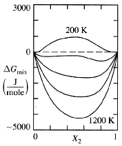
Figure 1: Plotting Gmix vs. Composition for Various Temperatures
This section will describe how the free energy of mixing of a system is used to create phase diagrams.
The free energy of mixing of a system, Gmix, depends on many conditions such as temperature, pressure, and composition. However, in most engineering situations it is easy to eliminate many of these variables. For example, pressure is not an important consideration in the steelmaking process, since it is assumed that the plant would be operating at ambient air pressure. So, let's consider a system where all variables can be considered constant except temperature and composition. By calculating the graphs of Gmix vs. composition for a number of temperatures, one can generate a family of Gmix vs. composition curves like those shown in Figure 1:
Figure 1: Plotting Gmix vs. Composition for Various Temperatures
For a given temperature, each possible phase in a given system will have its own Gmix vs. composition curve. The system has a variety of different states it could take on: during processing a metal could be liquid or solid, ordered or disordered; Gmix determines which state the system will choose. At that particular temperature the system will seek the lowest total free energy; which is to say it will become the phase with the most negative Gmix. For example suppose there existed a system which could exist as either a liquid or a solid phase called alpha:
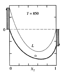
Figure 2: Gmix Curves for Two Phases
The above figure suggests that it is possible to calculate the change in free energy of the system as a liquid. However, for this particular temperature the Gmix of alpha is always more negative, regardless of composition. Therefore the system would rather be in the alpha phase no matter what the composition is.
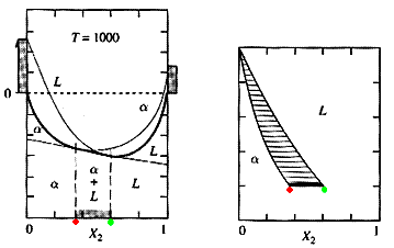
Now let's assume we took the previous liquid/alpha example to a temperature high enough to melt the entire sample, then cooled it. In the melted state, the Gmix line of the liquid will be below that of the liquid (the opposite of figure 2). As we decrease the temperature, there may be compositions where Gmix curve of the alpha phase is more negative than the liquid phase. Now the structure of the system does depend on composition. At certain compositions, the system will want to remain a liquid; at others, the solid phase is favorable. When the Gmix curves do cross, it is possible to draw a line that is tangent to both curves:
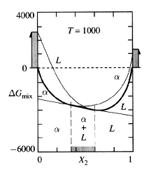
Figure 3: Crossing Gmix Curves
The tangent seems to bridge between the two curves; it becomes the line with the lowest Gmix. For any composition between the two tangent points, the optimum Gmix will now lie on the tangent line between these points. It is within this range of compositions that the two phases will exist in equilibrium. As temperature continues to decline, the compositions marking the two-phase region will change. By plotting these compositions at the temperature where they occur, a phase diagram can be generated:
Under certain conditions a miscibility gap may form. Under the right conditions, the heat of mixing can begin to dominate the free energy calculations. When this occurs, the Gmix curve of a phase can change concavity and take on a "camel-hump" appearance. The result is a region where two phases will form from a previously one-phase system:
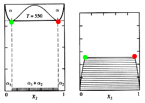
Figure 5: The Formation of a Miscibility Gap: Movie
Miscibility gaps can be seen in applications of all areas of materials engineering, but are especially important in polymers. Many polymers will mix into a single phase at elevated temperature, but the disassociate as the system cools.
Miscibility gaps are actually very common and occur in the majority of the systems you have studied so far. In fact, the miscibility gap is responsible for the production of one of the first phase diagrams you studied: the binary eutectic diagram. The binary eutectic is actually the combination of three separate two-tangent constructions: two two-phase constructions such as the ones in Figure 4, and a miscibility gap. Figure 6 shows how they interact to form the familiar shape of the binary eutectic:
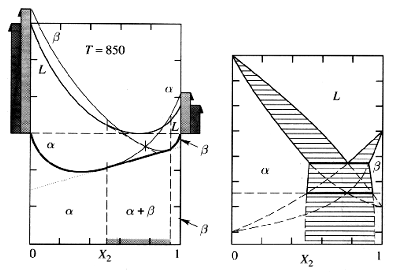
Figure 6: The Creation of a Binary Eutectic Diagram
The two-tangent construction of a phase diagram is an interesting example of how complex mathematics and delicate chemical interactions lead to the information materials engineers use every day on the job. Whether smelting tons of steel, preparing a small batch of a specialized superalloy, or preparing a polymeric adhesive, all systems must obey the laws of free energy. And by using these laws the behavior of even the most complex systems can be predicted.
http://www.eng.vt.edu/eng/materials/classes/MSE2094_NoteBook/
96ClassProj/analytic/cutter.html